
Once you have built your HO scale slot car track you will want to think about adding a lap counter and timer. Most lap counter software requires a personal computer running either MS DOS or the Microsoft Windows operating system. These software programs normally count and time laps using an interface cable connected to either the printer port or the joystick interface.
Note: The information provided here can also be applied to 1:32 and 1:24 scale slot car tracks as well as HO layouts.
See the Construction section of this web site for detailed photographs of how a lap counter and timer can easily be installed in your layout.
Computer Interfaces
The diagrams below illustrate the various port interfaces possible using an MS DOS or Microsoft Windows based computer system. Wiring diagrams are shown for the Joystick Game Pad Interface, The Parallel Printer Port and the Serial I/O Port.
Joystick Interface
The diagram below illustrates a typical slot car lap counter interface using the joystick game port found on most personal computers. The longer lead on the photo-cell (Emitter) is connected to the common signal ground (pin 4).
The numbered connections running down the left edge of the wiring diagram correspond to the numbered pins on the Joystick Game Port connector. The four sensors numbered Lane 1 – 4 correspond to the switches or photo-cells needed for each lane on your slot car track.
The 100K Ohm resistors aren’t used by the lap counter itself, but must be included to represent the X- and Y-Axis potentiometers found in a joystick device. Without them MS Windows can not detect a joystick device connected to the game pad port.
Warning: Run two separate wires from each sensor at the track all of the way back to the connector at the computer. Do not tie the ground lines (pin 4) together under the track.
If your PC has a multi-media sound card installed check the connectors at the rear of this card, most sound cards have an integral 15-pin joystick game port built in. The standard joystick game port can handle up to four “fire” buttons, that is enough for a simple four lane lap counter. If your computer does not have a joystick game card installed you can purchase one for as little as $25.00 dollars.
You will also need to configure MS Windows to recognize the joystick interface cable you’ve built. Follow the instructions described in the Joystick Configuration section to define a suitable device.
Printer Interface
The diagrams below illustrate typical slot car lap counter interfaces using the Parallel Printer Port found on most personal computers. The longer lead on the photo-cell (Emitter) is connected to the common signal ground (pin 25).
The wiring diagrams above illustrate typical 4-lane lap counter interfaces. The numbered connections running down the left edge of the wiring diagram correspond to the numbered pins on the Parallel Printer Port connector. The four sensors numbered Lane 1 – 4 correspond to the switches or photo-cells needed for each lane of your slot car track.
Warning: Run two separate wires from each sensor at the track all of the way back to the connector at the computer. Do not tie the ground lines (pin 25) together under the track.
Note: Pins 18 – 25 on the standard LPT port are all grounded, so you could just as easily used separate ground pins for each of the four sensor lines.
Serial I/O Interface
The diagram below illustrates a typical slot car lap counter interface using the Serial I/O Port found on most personal computers. Both DB-25 and DB-9 connectors are shown below. Most lap top computers use the smaller DB-9 connector, while full-sized desktop system usually have DB-25 connectors.
The wiring diagram above illustrates a typical 4-lane lap counter interface. The numbered connections running down the left edge of the wiring diagram correspond to the numbered pins on the Serial I/O Port connector. The longer lead on the photo-cell (Emitter) is connected to the common signal ground (pin 7 or 5).
Warning: Run two separate wires from each sensor at the track all of the way back to the connector at the computer. Do not tie the ground lines (pin 5/7) together under the track.
Track Switches & Sensors
Several different methods are available for detecting when a slot car passes over the start/finish line of your slot car track. These approaches break down into two basic categories; electro-mechanical and optical. Of the two, optical detection is the better choice.
Dead Tracks
The Dead Track method requires a specially made section of straight track as illustrated below.
Two 5/8″ sections of each rail must be removed to create a short dead rail approximately 3″ in length. The two red wires in the diagram above are connected to the joystick game port interface card to create a “switch”. When a slot car passes over this section of track the pickup brushes and motor “close” the switch.
Because you have cut the lane rails to create a dead section you will need to also tie the power rails back together with short jumper wires. The blue wires in the diagram above allow power to flow around the dead section.
There will be a momentary loss of power to a slot car as it passes over this dead section of track. To avoid stalls you should place your dead track section along a fast straight.
Tip: The easiest way to create a dead track section is to use a 6″ section of straight track with 5/8″ sections removed from the rails at both ends of this piece of track. Position this dead track section between two straight tracks wired as power terminal sections. See the Power section of this web site for further instructions on making power terminal tracks and dead sections.
Warning: Dead Track sections can be harmful to the printer and serial ports. DC motors act like DC generators when they spin freely, so dangerous voltages (Back-EMF) can be induced into the signal lines as cars coast over the dead section.
Note: The Joystick interface has isolated inputs that protect the port from these dangerous and potentially damaging DC pulses, but printer and serial ports do NOT.
Photo-Cells
The Photo-Cell Switch method requires a small 1/8″ hole to be drilled between the guide pin slot and one of the power rails. The photo-cell is mounted under the track facing up through the hole you drilled. The photo-cell leads are then connected directly to the joystick game port interface board.
See the Construction section of this web site for detailed photographs of how the photo-cells can be mounted under the track.
I sell 2- and 4-Lane Photo-Cell Cables with your choice of Joystick or Printer port interfaces in the Lap Timer 2000 Cable Kits section at the end of this page.
Photo-cells are sensitive to the infra-red (heat) portion of the light spectrum. Any small incandescent lamp will produce enough heat energy to work properly.
Fluorescent light however does not contain enough infra-red energy to work reliably.
If you plan to use IR-LED devices as emitters keep in mind when wiring and testing that they produce no visible light, but will produce infra-red energy suitable for use with photo-cell detectors.
A light source must be placed directly above the section of track containing the photo-cell switches. Each time a car passes over the photo-transistor the light beam will be broken causing the switch to close.
Magnetic Reed Switches
The Magnetic Reed Switch method requires small magnetic reed switches to be placed under each lane. As a slot car passes over this section of track the slot car’s motor or traction magnets momentarily closes the reed switch.
Reed Switches suitable for lap counters are available in the Lap Timer 2000 Components section at the end of this page.
Orientation of the reeds inside the switch itself is very important. Make sure you install the reed switches so that the two moving blades are positioned next to one another like the diagram below.

When a slot car passes over the reed switch the two blades should move from side to side, not up and down. If installed incorrectly the strong magnets used in slot cars will pull the upper blade away from the lower blade instead of drawing them together as they were designed to operate.
Scalextric Lap Counter
Racers with Scalextric 1:32 scale slot car tracks can use the Scalextric RMS Multi-Lane Extension Kit (C.8147) with integral mechanical reed switches to count and time laps on Scalextric Classic and Sport tracks.
The diagram below describes the pinouts for the standard mini-phone plug the track section uses to connect to an external lap counter.
The Scalextric RMS Multi-Lane Extension Kit is a 2-lane track section. For tracks with more than two lanes use one lap counter section for each two lanes.
Implementation
Of the three lap sensor types described above, the Photo-Cell method is the best. The Reed Switch and Dead Track methods are problematic with older Aurora Model Motoring Thunderjet slot cars that don’t employ traction magnets, and can also be unreliable with fast-moving modern slot cars.
For 1:32 scale tracks the Scalextric RMS Track Expansion Kit with internal switches is extremely reliable.
Timing Gantry
If your room light is low or you have Fluorescent ceiling lights you may want to create a small bridge or timing gantry spanning that portion of track containing the photo-cells. The underside of the bridge can contain high-intensity lamps or Infra-Red LED devices that shine directly down on the photo cells. This method also prevents false triggers if racer’s shadows fall on the photo cells.
Your local Radio Shack sells photo-cells that are ideal for use as slot car lap counters. Ask the clerk for RS Part No. 276-145.
If you elect to build the timing gantry as well, Radio Shack makes matching high-output Infra-Red LEDs for mounting on the underside of the gantry. Ask the clerk for RS Part No. 276-143.
The diagram below illustrates the power supply and wiring required to build a 4-lane timing gantry. The current limiting resistors are connected to the Cathode (negative) side of the infra-red LED devices.
The picture below illustrates an easy and attractive means of incorporating a timing gantry using a simple pedestrian foot bridge. The LEDs can be mounted under the bridge itself, shining down towards the photo-cells mounted under the track. This timing gantry was built using an HO Pedestrian Bridge painted white. I sell this Pedestrian Bridge in the Lap Timer 2000 Components section at the end of this page.
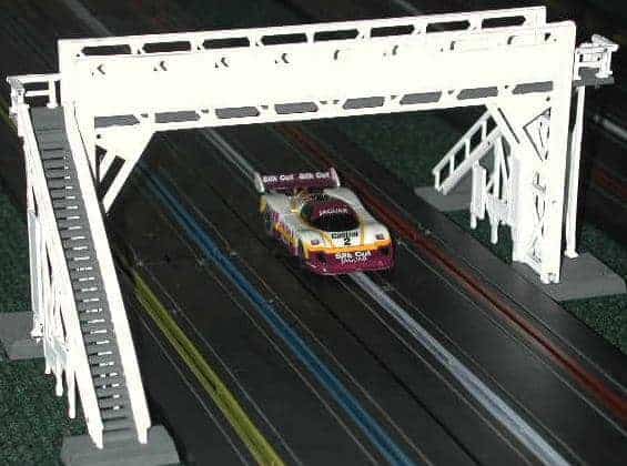
This bridge is ideal for an HO scale raceway. The bridge section itself is just over 6 inches wide, allowing it to easily span a 4-lane straightaway. The billboard sections on either side of the walkway are perfect for sponsors’ decals or your raceway’s name.
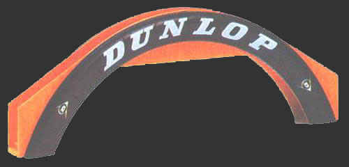
I also sell the attractive 4-Lane Dunlop tire Bridge shown above in the Lap Timer 2000 Components section. This bridge works well for raceways with a European sportscar or long distance endurance racing theme. This bridge is a replica of the famous footbridge at Le Mans.
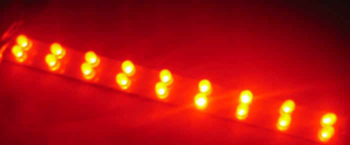
I have a pre-assembled LED bar with 18 Red LED devices mounted on a narrow circuit board that works perfectly as a timing gantry. This circuit board is powered by any 12 VDC power pack producing at least 200 mA. See the Lap Timer 2000 Components section at the end of this page.
Racers with 1:32 or 1:24 scale tracks can eliminate the overhead timing gantry completely by mounting the IR LED emitter on one side of the slot and the photo-cell on the other side. Enclosing the entire system under the track is much neater and more reliable. The guide flag itself acts as a shutter when it passes between the emitter and detector. The Ninco electronic lap counters use this same approach.
USB & Lap Top Users
Many newer Lap Top computers no longer provide printer or joystick ports, but instead offer USB interface capabilities. Radio Shack sells a USB/Joystick adapter that will allow you to use the USB port on your Lap Top computer with a Joystick Interface cable.
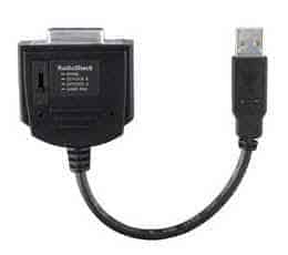
Ask your local Radio Shack salesman for RS part number 26-728 or 26-164.
Track Power Relay Wiring
Lap Timer 2000 can be used to turn track power on and off automatically. This is best accomplished with a DC/DC Solid State Power Relay. These devices have very low trigger current requirements and will work with any lap top or desktop computer having an LPT port.
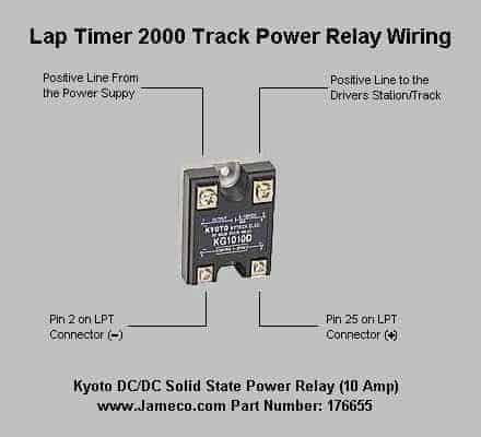
Track power will automatically be turned on when a race is started, and off at the end of the race, or whenever the Race | Pause command is issued.
MS Windows Software
I have written a small MS Windows program to count and time laps on race tracks with up to 4 lanes. The software is free and may be copied and distributed as long as all copyright notices remain intact and the application files are not modified in any way.
This computer software is designed to work with any MS Windows 95/98/ME/XP/NT/2000 computer system. Lap Timer 2000 includes interfaces for both the serial, and parallel printer ports as well as a PC keyboard and the standard joystick game port.
The screen shot below illustrates the Lap Timer 2000 main window. The current lap time is displayed using a large 90 point font to facilitate easy viewing from across a room. The current lap time displayed for each lane is updated each time a slot car passes over the lap counter track. The current Lap No. will also be updated when a slot car passes over the lap counter.
The Lap Timer 2000 main window is actually 700×555 pixels in size.
Up to four (4) lanes may be simultaneously monitored and displayed. The background color of each lane’s display can be configured by the user to reflect the actual lane color coding used. The Best Lap region records the fastest lap time recorded during the current session. A single race or practice session can record up to 4096 laps per lane. An optional Average MPH/KPH speed can also be displayed. This information will appear in-between the Lap No. and Best Lap display regions for each lane.
For accurate average lap speed calculations you must specify the scale of your slot cars and the running lap length for each lane. Distances and speeds can be defined in either U.S. (Imperial) or Metric units of measure.
You may also view a detailed report listing all lap times recorded for each lane during the current session using the View | Lap Times… menu command.
Races can be run for a specified length of time or until a preset number of laps have been completed. A race summary file is created when a race is completed. This race summary file can be viewed or printed. The race summary includes the number of laps completed as well as individual lap times for each competitor. Here is a Sample of the Race Results File that Lap Timer 2000 generates.
Click your mouse on the program title below to download the latest release of Lap Timer 2000.
Download Lap Timer 2000 Lap Timer 2000 v6.3 (616K)
LapTimer 2000 includes TrakMate compatibility, support for MS Windows XP, race pause and resume facilities and an extensive help file with interface cable building instructions and wiring diagrams.
You can purchase ready-made Lap Timer 2000 interface cables or make your own using the information provided earlier on this page.
The interface cables sold below include photo-cells which are mounted under your slot car track. The photo-cells are connected to s small junction box that is mounted under the table. The junction box included in the interface kit uses a standard RJ-45 modular network jack. The kit also includes an 8 foot Cat-5 Network cable and a Printer or Joystick connector with an RJ-45 jack enclosed in the plastic hood. Software is provided on a 3-1/2″ disk as well.
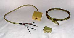
These interface cables require no assembly or soldering. Simply mount the photo-cells under your track, attach the junction box to the underside of the table and plug the included cable into the junction box and the port on the back of your computer.
See the Construction section of this web site for step-by-step installation instructions and some photographs of these interface kits.
Lap Timer 2000 Cable Kits
Lap Timer 2000 4-Lane Printer Kit
Lap Timer 2000 2-Lane Printer Kit
Lap Timer 2000 4-Lane Joystick Kit
Lap Timer 2000 2-Lane Joystick Kit
Lap Timer RMS 2/4-Lane Printer Kit
Lap Timer RMS 2/4-Lane Joystick Kit
Note: Lap Timer 2000 does not work with the Scalextric Sport RMS base module, however it can be used with the Scalextric Sport RMS Multi-Lane Extension Kit C.8147. These are the track sections with mechanical reed switches mounted under each lane.
The Lap Timer RMS 2/4 Lane Printer and Joystick Cables will allow you to use up to two (2) of the Scalextric C.8147 units to count and time laps on slot car tracks with up to four lanes.
These cables are terminated with two (2) mini-phone jacks that the standard Scalextric units will plug right into.
If you’re not familiar with solid state electronics and wiring techniques then these Miniature 12 VDC Lamps & Sockets are a good choice for building a timing gantry.